
Maximum Simultaneous Operations Limiter using PLC
Introduction
Theory :
In many applications there will be limit on the current drown, in such cases maximum simultaneous operation limiter is required. In our experiment, there are three motors, each with its own start-stop buttons. Any two may run at a time. Also any one may run by itself.
Introduction To Logic :
A hardwired control circuit can be represented by conventional hardwired relay ladder diagram. In any hardwired circuit, there should be electrical continuity in order for the load to energize.
Basics about conventional ladder and PLC ladder logic :
Electrical sequence of operation in hardwired relay circuits can be represented by electrical ladder diagram. Ladder diagram shows the interconnection of field devices. In the ladder diagram, each rung shows how a field device is turned on and also shows how it interacts with next field devices.
The difference between a PLC ladder program and relay ladder rungs is the continuity. In an electrical rung diagram, there is an electrical continuity only when the current flows from left power rail to right power rail.
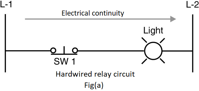
Fig (a), shows electrical continuity when SW 1 is closed, as the current flows from L-1 to L-2 energizing the load.
Even though PLC ladder logic was modeled after the conventional relay ladder, there is no electrical continuity in PLC ladder logic. PLC ladder rungs should have logical continuity in order for the output to energize. PLC ladder program uses familiar terms like "rungs" and "normally open" and "normally closed" contacts, but the relay ladder logic has no electrical continuity between an input and the controlled output.
Note:- There is no physical conductor that carries the input signal through to the output.
Each rung in a ladder diagram is a program statement. This program statement consists of a condition or sometimes conditions, along with some type of action. Inputs are the conditions, and the action, or output, is the result of the conditions.
As in case of physical wiring hardware devices connected in series or parallel, PLC also combines ladder program instructions in series or parallel. However, rather than working in series or parallel, the PLC combines instructions logically using logic operators. Logical operations performed by PLC are nothing but fundamental logic operation, using fundamental logic operators like: AND, OR, and NOT. These operators are used to combine the instructions on a PLC rung so as to make the outcome of each rung either true or false.
The AND-logic function :
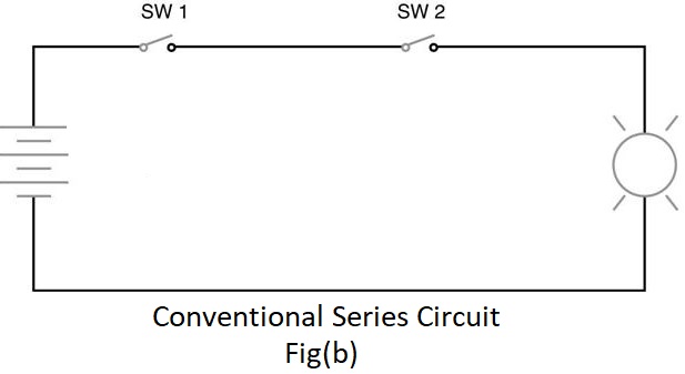
The series circuit of 2 switches can be looked as an AND logic function. In fig (b) and fig (c), both switch1 and switch2, must be closed to have electrical continuity. W hen there is electrical continuity, output (light1) will energize. Hence the keyword here is AND.
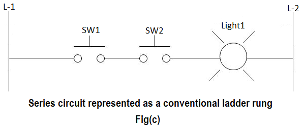
The circuit in fig (b) is represented as a schematic diagram ladder rung in fig (c).
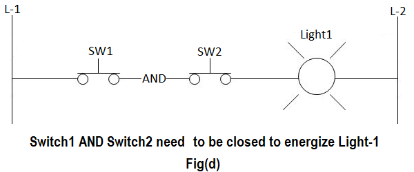
When the switch1 and switch2 is closed, electrical continuity is established to L-2. This is shown in fig (d).
The various possible switch combinations are shown in the truth table below.
Table 1: Truth table for AND logic
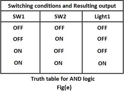
Fig (d) can be written in PLC ladder format as shown in the figure below
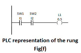
Here is the program listing for a typical PLC, if you are entering the program with a handheld programmer.
LOAD I1
AND I2
OUT O5
The above instruction tell the processor to load input 1 (I1) into memory, AND it with input 2 (I2) and then output the result to output 5 (O5). The resulting output will be based on the truth table fig (e).
The OR-logic function :
In an OR - LOGIC function, the output is true if any input is true. The OR logic also states that if all inputs are true, the output will be true.
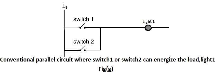
In the above figure, if switch1 OR switch2 is energized then light1 will energize. Also, if both SW 1 and SW2 are true, the output will also be true.
Fig (g) is converted to PLC ladder rung and it looks like fig (h)
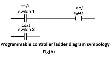
A PLC rung of logic will have normally open or normally closed contacts instead of normally open or normally closed switch symbols. Addresses and instructions are included. Here, in additions to each contact and its address, text information such as SW1, SW2 and L-1 is used and they are referred to as instruction comments. These instruction comments can be added from programming software.
Table 2: Truth table representing two-input OR function
The NOT-logic function :
A normally closed relay contact passes power any time when the relay coil is not energized. In the same manner, the normally closed PLC ladder logic instruction will pass power any time when the input status file bit associated is not a 1. In this condition, the physical hardware input is not sending an input signal into the PLC's input module. The opposite of normally open PLC instruction or contact is the NOT logic. NOT logic can be used in conjunction with AND or OR logic, when a logical 0 in the status file is expected to activate some output device. In other words, NOT logic is used when an input is not energized i.e., 0 in the associated status bit, the output should be energized. Also, when the input is energized i.e., 1 in the associated status bit, the output should not be energized.
Table 3: Truth table for NOT function
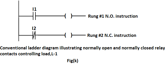
Analysis of rung 1 :
When I1 is true i.e. the input status file bit regarding I1 is true (1), the instruction I1 will energize the output. The instruction I1 is considered true when it passes logical continuity. If there is no valid input signal from the field input devices attached to I1's screw terminal on the input module, a logical 0 will be placed in the associated input status file bit. A logical 0 in the input status file will make the normally open input instruction to become false. When normally open instruction is false, it will not pass logical continuity.
Analysis of rung 2 :
The normally closed instruction works much like normally closed contacts on a hardware relay. In the fig (k), when the normally closed instruction I2 is true, i.e. the associated status file bit has a valid zero (0), logical continuity is established to energize the output. When the associated status file bit has valid 1, the NC instruction goes false and there is no logical continuity and the output is not energized.
The PARALLEL NOT- logic function :
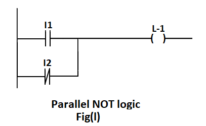
PLC ladder rung has 2 input instructions, one normally open and the other one is normally closed. This circuit contains parallel NOT logic. This schematic rung will be true under the conditions shown in the truth table below.
Table 4: Input and output relation of a parallel NOT function.
Output L-1 will be energized only when input1 must be true OR input2 must not be true.
The EXCLUSIVE OR-logic function :
Table 5: Input and output relation of an exclusive OR function.
Ladder rung of EXOR GATE would look like this
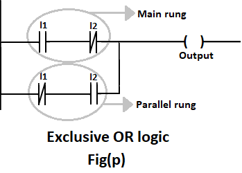
Case 1 : :
When I1 = 0 and I2 = 0:
Let us analyze main rung. When I1 = 0, the normally open instruction is false and, normally closed instruction is true, but since normally open instruction is false, there is no logical continuity and output cannot be energized. Similar analysis can be done in parallel rung, normally closed instruction will be true and normally open instruction will be false and output is not energized.
Case 2 :
When I1= 0 and I2 = 1:
In main rung, normally open instruction will be false and, normally closed instruction will be true, but since there is no logical continuity this rung logic cannot energize the output. But, in parallel rung, normally closed instruction will be true, as well as normally open instruction will also be true, hence there is logical continuity, and output is energized.
Case 3 :
When I1 = 1 and I2 = 0:
This case is similar to case 2, only the role of inputs are interchanged i.e. here main rung is true and energizes the output and parallel rung is false.
Case 4 :
When both inputs are true, the main ladder rung as well as the parallel ladder rung goes false. In main rung, normally open instruction is true but normally closed instruction is false. Hence, there is no logical continuity. In parallel ladder rung, normally closed instruction is false and normally open instruction is true, and here also there is no logical continuity. Hence, the output is not energized.
TIMERS :
All PLC’s have timer instructions. Timers are output instructions that are internal to the programmable logic controller. Timers provide timed control of the devices that they activate or de-activate.
Basic functions of timer :
- Timers are used to delay an action.
- Timers are used to run an operation for a predetermined period of time.
- Timers are also used to record the total accumulated time of continuous or intermediate events.
Timer’s instructions :
Timers consists of following parts: timer address, preset value, timer base, and accumulated value, as shown in
figure below.
In the above figure , term instruction name is, timer on delay ( TON ), timer base is 1.0 seconds, timer address is T4:0, accumulated value of zero(0) and a preset value of 200.
Each timer instruction has three very useful status bits. These bits are timer enable (E N), timer timing (TT), and timer done(DN).
There are 3 types of timers: On- delay timer, Off-delay timer, and retentive timer.
On delay timer :
- Use this instruction to program a time delay after instructions become true.
- On – delay timers are used when an action is to begin a specified time after the input becomes true. For example, a certain step in the manufacturing is to begin 45 seconds after a signal is received from a limit switch. The 45- seconds delay is the on-delay timers preset value.
Off- delay timer :
- Off- delay timer instructions is used to program a time delay to begin after rung input goes false.
- As an example, when an external cooling fan on a motor is provided, the fan has to run all the time the motor is running and also for certain time (say 10min) after the motor is turned off. This is a ten minute off- delay timer. The ten-minute timing period begins as soon as the motor is turned off.
Retentive timer :
- Retentive timer is a timer which retains the accumulated value in case of power loss, change of processor mode or rung state going from true to false (rung state transition).
- Retentive timer can be used to track the running time of a motor for its maintenance purpose. Each time the motor is turned off, the timer will remember the motor’s elapsed running time. The next time the motor is turned on, the time will increase from there. This timer can be reset by using a reset instruction.
Reset :
- This instruction is used to reset the accumulated value of counter or timer.
- It is used to reset a retentive timer’s accumulated value to zero.
A typical timer element:
A timer element is made up of three 16 bit words:
- Word 0 → 3 status bits (EN, TT, DN).
- Word 1 → Preset values.
- Word 2 → Accumulated value.
How do we address a timer?
Addressing a timer is as follows:
- The address format in order to address the timer element is T4:3
Where, T = T identifies this as a timer file.
4 = represents the default timer file 4.
Note: SLC timer can be assigned any unused file from 9 to 255.
:3 = This is timer three in file 4. There are 256 timers available in each file. Timers 0 through 255 are available .
- Preset value of the timer can be addressed in the following way:T4:3.PRE
Where, T= identifies this as a timer file.
4= represents the default timer file 4.
:3= timer 3 in file 4.
. = this point is the word delimiter. It separates the timer number, called the structure, from the subelements. Here the subelement is PRE, for preset value.
- Accumulated value of the timer can be addressed as shown below:T4:3.ACC
Where, T= identifies this as a timer file.
4= represents the default timer file 4.
:3= timer 3 in file 4.
. = this point is the word delimiter. It separates the timer number, called the structure, from the subelements. Here the subelement is ACC, for accumulated value.
⇒ The status bits of the timer can be addressed in the following way:
- Word zero, bit 13, is the done bit. It is identified as DN. This bit is set when the timer’s accumulated value is equal to the timer’s preset value. It can be addressed as T4:3/DN.
- Word zero, bit 14, is the timer timing bit. It is identified as TT. TT is set when the timer is timing. It is addressed as T4:3/TT.
- Word zero, bit 15, is the timer enable bit. It is identified as EN. EN bit is set whenever the timer is enabled. It is addressed as T4:3/EN.
The on-delay timer instruction :
The above figure is used to explain the on-delay timer instruction.
Here, T4:2 represents timer file 4, timer element 2, preset value is 50, accumulated value is 0 and timer base is 1 second. Input module is in slot 1 and output module is in slot 2.
- As long as the instruction I:1/0 is true, the on-delay timer T4:2 will increment every one second toward its preset value of 50 seconds. The accumulated value displays the current number of seconds that passed. When the accumulated value is equal to the preset value, the timer’s done bit will get energized or set. So when the timer’s done bit gets energized, the rung 003, instruction T4:3/DN becomes true and logical continuity is passed and the output O:2/2 gets energized.
- As long as the I:1/4 is true, the timer instruction is enabled. Hence, rung 000 becomes true and logical continuity is
passed and the output O:2/0 is energized.
Note: An on-delay timer is not retentive in nature.so any loss of continuity to the timer instruction on rung 000 will cause the timer to reset itself to an accumulated value of 0. - When the timer is timing i.e rung 000 is true and accumulated value is less than preset value, timer timing bit(TT) is true.
So the rung 002 becomes true i.e instruction T4:2/TT is true and output instruction O:2/1 is energized.
Note: As long as the rung 000 is true i.e instruction I:1/0 is true, the timer instruction is considered enabled. The enable bit will be true when the timer timing bit is true. Timer enable bit will be set through the transition from the timer-timing bit to the timer-done bit. Timer enable bit is set as long as there is logical continuity through all input instructions to the timer instruction, no matter the relationship between the preset value and accumulated value. When the rung goes false, the enable bit is reset.
The off-delay timer instruction :
The above figure is used to explain the off-delay timer instruction. Here, T4:2 represents timer file 4, timer element 2, preset value is 200, accumulated value is 0 and timer base is 1 second. Input module is in slot 1 and output module is in slot 2.
- As an example, consider an external cooling fan on a motor which has to run all the time when the motor is running and also for 200 seconds after the motor is turned off. For this purpose, we use 200- second off-delay timer. The 200-second timing cycle begins when the motor is turned off.
- When the instruction I:1/0 is true, the motor is turned on i.e instruction O:2/0 becomes true. In other words, rung 000 becomes true. When the instruction I:1/0 is true, rung 001 becomes true, which will make the off-delay timer T4:2 enable. So as long as the instruction I:1/0 is true, the timer enable bit, EN, is true and hence, rung 002 become true, which inturn makes the output instruction O:2/1 true. The done bit is set as long as the rung 001 is true i.e the done bit is set when the enable bit is set. So the rung 004 is true. Hence, the external cooling fan is energized i.e instruction O:2/3 is true. So at this point, both motor and external cooling fan are energized.
- When the motor is turned off, i.e the instruction I:1/0 becomes false, the output instruction O:2/0( motor) becomes false
and motor is turned off. When rung 001 transitions from true to false, the TOF( off-delay timer) instruction begins timing.
The done bit and the external cooling fan( O:2/3) will still remains on, or true, for the preset value of 200 seconds. The time
period between the point when the rung becomes false and the point when the 200 seconds preset time expires for T4:2 is
called delay after the input goes false, or the off-delay. The timers done bit and its associated output stay true until the
off-delay of 200- seconds expires. The time expires when the accumulated value reaches the preset value. When the input
instruction I:1/0 goes from true to false, the timer enable bit (EN) is reset and timer timing bit(TT) is set. The timer will start
timing at this point. The timer timing bit(EN) becomes true whenever the rung transitions from true to false and the
accumulated value is less than the preset value.
Note: The timer done bit, bit 13, is set when the rung 000 becomes true. It will remain set through the true to false transition and until the accumulated value is equal to the preset value. This bit is commonly used to control the other logic when an output needs to be turned-on or turned-off after its rung has been off for the preset time interval.
The retentive timer instruction :
Retentive timer instruction is used when we want to retain the accumulated value through power loss, processor mode change, or change in the rung state from true to false. The retentive timer instruction will measure the cumulative time period for which its rung is true. One of the example of retentive timer is that, it can be used to track the running time of a motor for maintenance purpose. The retentive timer is used to track the accumulated time the motor has run. In our example , our motor needs maintenance after 3600 seconds or, one hour of running time. Each time the motor is turned off, the timer needs to remember the motors total elapsed running time. The next time the motor is turned on, the timer will increase the accumulated running time from where it is left off. When the total accumulated motor running time has been reached, a maintenance remainder pilot light will be lit. A retentive timer is used in this application.
Here, T4:2 represents timer file 4, timer element 2, preset value is 3600, accumulated value is 0 and timer base is 1
second. Input module is in slot 1 and output module is in slot 2.
The retentive timer on, RTO instruction, behaves similar to the timer-on delay instruction, with exception that when the RTO
instruction goes false, it will retain its accumulated value.
The retentive timer will retain its accumulated value during the following conditions:
- When its rung goes false.
- When processor losses power. But, the battery for memory back up must be in good condition.
- When the processor faults.
- When the processor operating mode is changed from remote run or remote test to remote program mode.
Associated status bit :
The timer done bit, bit 13, is set when the accumulated value is equal to the preset value. For our application, the done
bit and output O:2/0 could control the maintenance reminder pilot light.
Timer timing bit(TT), bit 14, is on rung 002. This bit is set anytime the rung conditions are true and the timer times. The timer
times whenever the rung is true and the accumulated value is less than the preset value. When the done bit is set, the
timer timing bit resets. So in our example, the timer timing bit will be set or true, whenever input I:1/0 is true and as long as
the accumulated value is less than the preset value of 3600 seconds. Output O:2/1 will be on or true when the timer is
timing between 0 second and 300 seconds. As the done bit is set and O:2/0 turns on, the timer timing bit goes false and
O:2/1 turns off.
The timer enable bit, 15, is set or true , anytime the timer instruction rung 000 is true. As long as the instruction I:1/0 is true,
the timer instruction is considered enabled. The enable bit is true when the timer-timing bit is true and it will stay set through
the transition from the timer-timing bit to the timer done bit.
The reset instruction:
In order to reset the accumulated value of retentive timer, a reset instruction is used. The address of the reset instruction must match the address of the timer that is to be reset. Only one address is allowed per reset instruction. In rung 004, I:1/1 instruction is used to reset the timer T4:2. This signal comes from a momentary normally open push button field device, connected to input screw terminal 1. Pressing this push button will reset the RTO’s accumulated value back to 0.
NOTE: Retentive timer off instruction behaves similar to the timer-off delay with the exception that when the instruction goes from false to true, it will retain , or remember, its accumulated value.